English
 Español
 中文简体

Home / News / Industry News / Class A vs Class AB Amplifier: Bias, Heat and Powered Speaker Trade-offs
For almost every powered speaker project, a well-designed Class AB stage is the safer engineering and commercial choice. Class A only wins when measured linearity at very low listening levels matters more than heat, weight and electricity cost. That single sentence explains why Class AB modules still sit inside most production loudspeakers, even though Class A carries the better reputation on paper.
The two classes are not different technologies. They are the same complementary transistor output stage, biased at different operating points. Everything else, from heatsink size to shipping weight, follows from that bias current.
Content
- 1 The Bias Point Decides Everything Else
- 2 Efficiency and Heat: The Cost of Never Switching Off
- 3 Distortion: A Good Class AB Usually Beats a Cheap Class A
- 4 Class A vs Class AB at a Glance
- 5 What This Means for Powered Speaker Module Design
- 6 Choosing Between Them for a New Product
- 7 Frequently Asked Questions
- 7.1 Q1. What is the main difference between a Class A and a Class AB amplifier?
- 7.2 Q2. Is Class A really better than Class AB for sound quality?
- 7.3 Q3. Why do Class A amplifiers run so hot?
- 7.4 Q4. Which is more efficient, Class A or Class AB?
- 7.5 Q5. Can a Class AB power amplifier module drive a subwoofer?
- 7.6 Q6. How do I size the power supply and heatsink for a Class AB module?
The Bias Point Decides Everything Else
In a Class A output stage the devices conduct for the full 360 degrees of the signal cycle. Quiescent current is set higher than the peak current the amplifier will ever deliver into its load, so the transistors never switch off. There is no crossover region, no hand-off between devices, and the transfer curve stays linear from a few millivolts upward.
Class AB sits between Class B and Class A. A small standing bias keeps both devices conducting for roughly 200 degrees of the cycle, just enough to overlap at the zero crossing and remove the notch distortion that plagues pure Class B. Outside that overlap window each device works only half the time, which is where the efficiency gain comes from.
The practical consequence is easy to observe on a bench. A Class A channel draws roughly the same power from the supply whether it is silent or running at full output. A Class AB channel draws little at idle and progressively more as output rises. That is why a Class A chassis is hot ten seconds after switch-on, while an AB chassis stays cool until the programme material arrives.
Efficiency and Heat: The Cost of Never Switching Off
Chart 1: typical full-power efficiency ranges taken from standard linear-amplifier design references
The theoretical ceiling for a Class A stage is 50% with a transformer-coupled load, and closer to 25% for the more common single-ended arrangement. Real designs settle in the 15-30% band. Class AB reaches about 78.5% in theory and delivers 50-70% in practice, which is exactly why it became the default for high-power analogue audio.
Translate that into a purchasing decision. A 200 W Class AB module might draw 300-350 W from the mains at full output and 20-30 W at idle. An equivalent Class A design needs a supply and heatsink sized for several hundred watts of continuous dissipation, which usually means three to four times the metal, transformer and cabinet volume per delivered watt.
Chart 2: standing dissipation follows bias current, not output level
Distortion: A Good Class AB Usually Beats a Cheap Class A
Class A's reputation rests on two real advantages: no crossover distortion, and a harmonic profile dominated by low-order, benign second harmonic. Both are genuine. But the comparison that matters in a product is rarely ideal against ideal.
Crossover distortion in Class AB shows up as high-order harmonics at low output levels, precisely where the ear is most sensitive. It is controlled by three things: enough bias current, tight thermal tracking of the bias network so the setting does not drift as the heatsink warms, and adequate loop gain. Executed properly, Class AB modules hold total harmonic distortion in the 0.01-0.05% range at rated power, which is inaudible in any normal playback context.
Where Class A genuinely pulls ahead is at milliwatt levels into high-sensitivity drivers. If your product is a near-field monitor for critical listening, that margin is worth paying for. If it is a portable PA box, a column speaker or a subwoofer, the difference disappears beneath room noise and programme material.
Class A vs Class AB at a Glance
The table below condenses the comparison into the parameters that actually drive a bill of materials and a thermal design.
| Parameter | Class A | Class AB |
|---|---|---|
| Conduction angle | 360 degrees, continuous | 180-360 degrees, about 200 typical |
| Full-power efficiency | 15-30% | 50-70% |
| Idle power draw | High, close to full-load draw | Low, rises with output |
| Distortion signature | Very low, second harmonic dominant | Low; crossover artefacts if bias drifts |
| Heatsink and transformer per watt | Three to four times larger | Baseline |
| Weight and footprint | Heavy, often two rack units or more | Moderate, easier to fit in a cabinet |
| Typical applications | Hi-fi, headphone amps, small monitors | PA speakers, line arrays, subwoofers, car audio |
| Cost at equal output | High | Moderate |
What This Means for Powered Speaker Module Design
Professional powered speakers, line arrays and subwoofers are built around Class AB, and increasingly around Class D and Class H, for one reason: a working product has to survive long duty cycles inside a hot rack. The thermal arithmetic above simply rules out Class A at the power levels those systems demand.
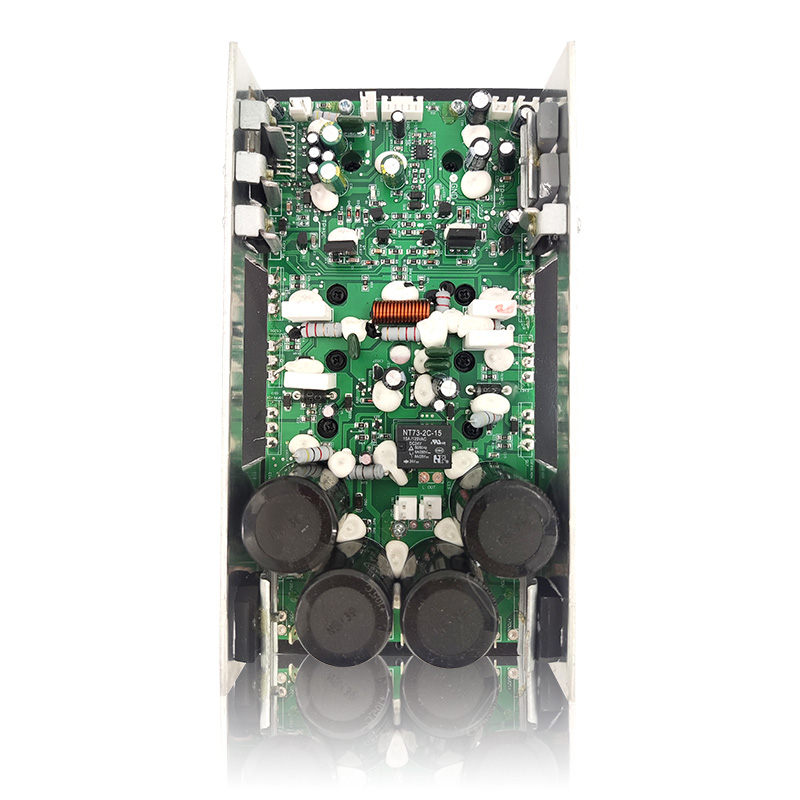
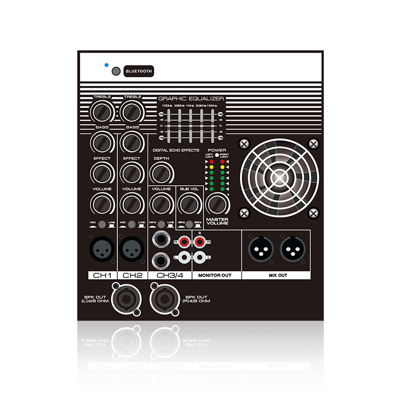
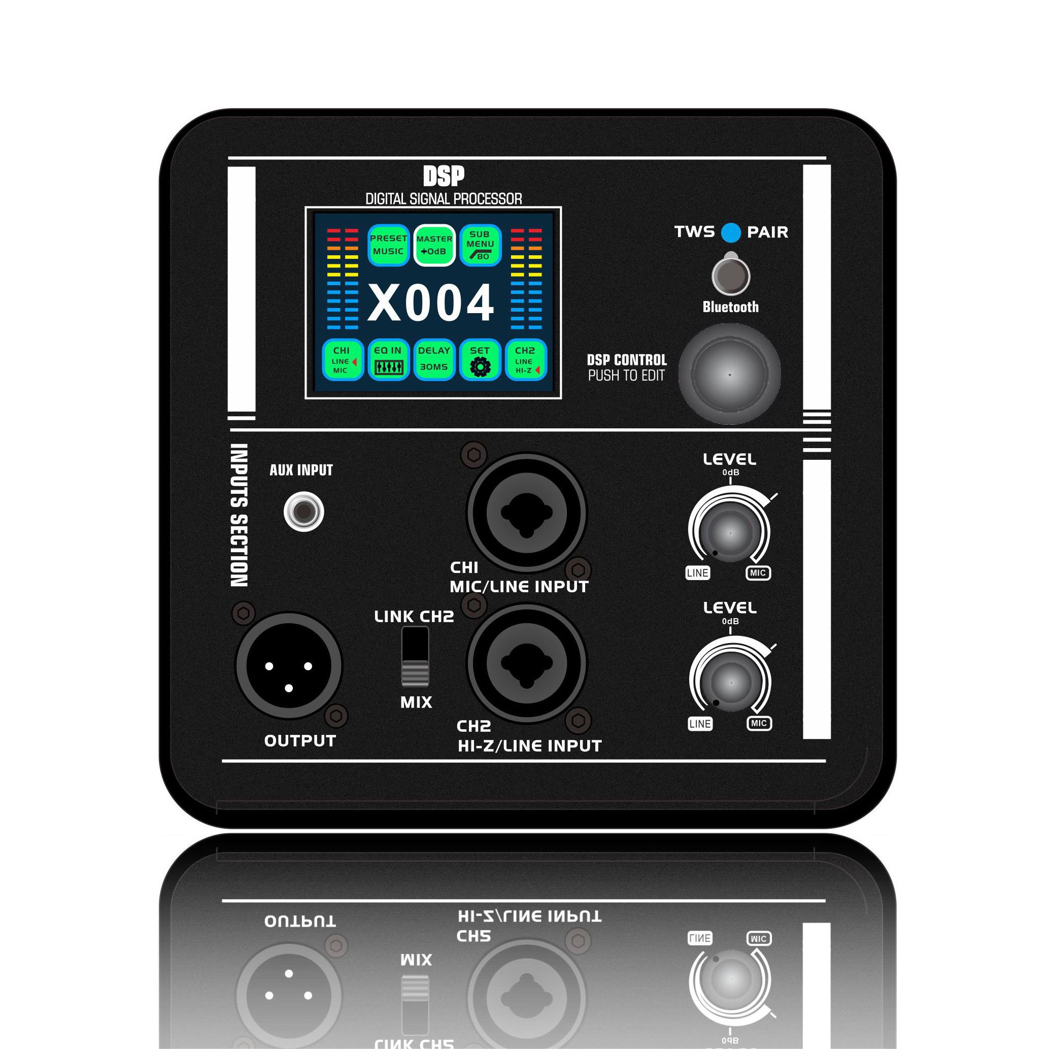
Inside a typical AB design the power amplifier module handles voltage gain and current delivery, while tone control, microphone input and limiting live on separate functional modules placed in front of it. That split keeps the analogue signal chain short and lets one amplifier platform be reused across several cabinet models.
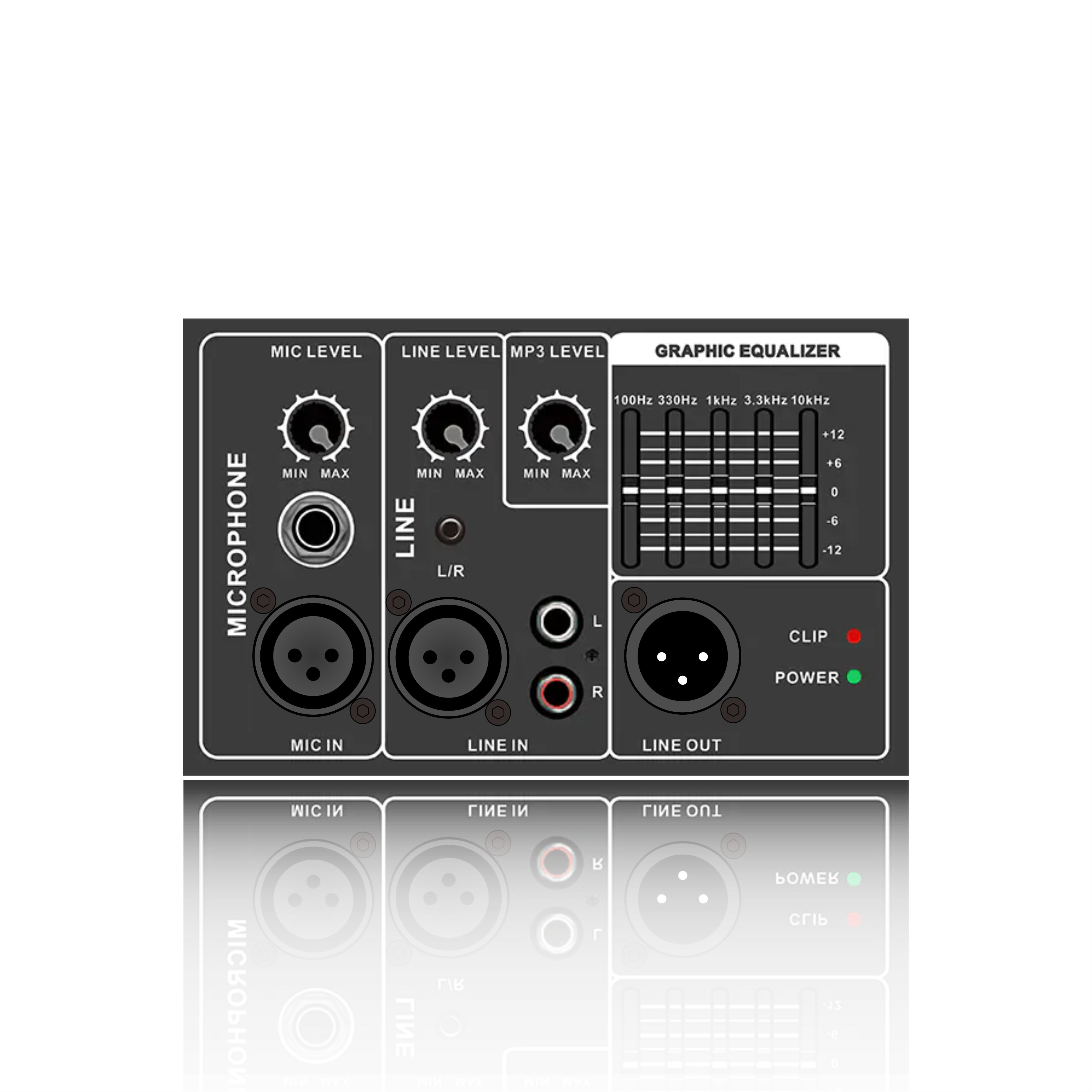 PL35 Horizontal Analog Front-End Module for Class AB AmplifiersBalanced microphone and line inputs plus a five-band graphic equaliser make this horizontal module a compact front end for Class AB amplifier platforms.View Product →
 PL21 / PL21E Vertical Functional Module with Limit ProtectionA vertical front-end option for narrow enclosures, combining balanced microphone and line inputs, a five-band equaliser and limit protection; PL21E adds microphone echo control.View Product →
The two front-end modules above follow that pattern: balanced microphone and line inputs with a five-band graphic equaliser in a horizontal format, or the same equaliser with limit protection in a vertical format when the enclosure is narrow. Both are designed for Class AB amplifier platforms, so the bias behaviour of the output stage stays the dominant variable.
Figure 3: how an amplifier plate stack is assembled in an analogue powered speaker
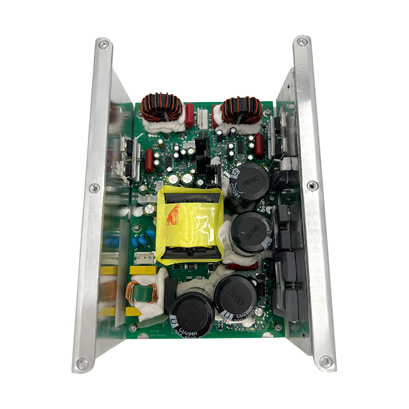
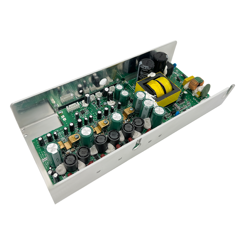
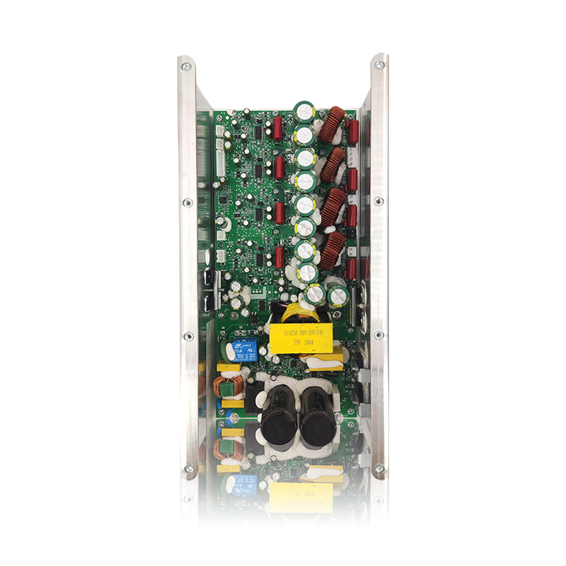
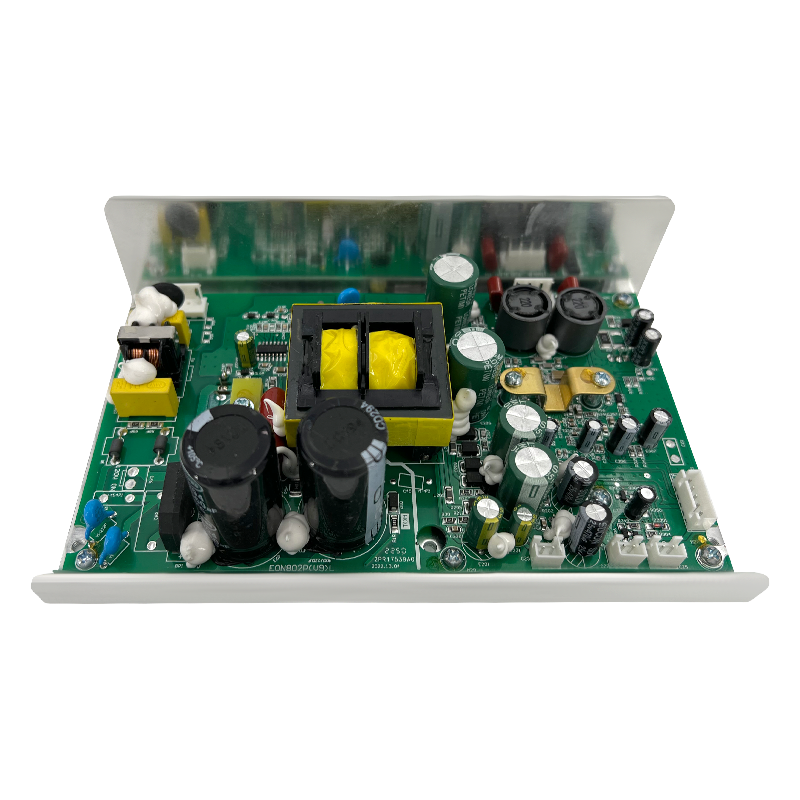
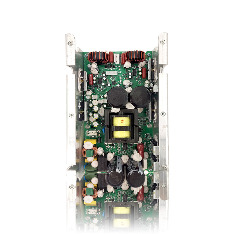
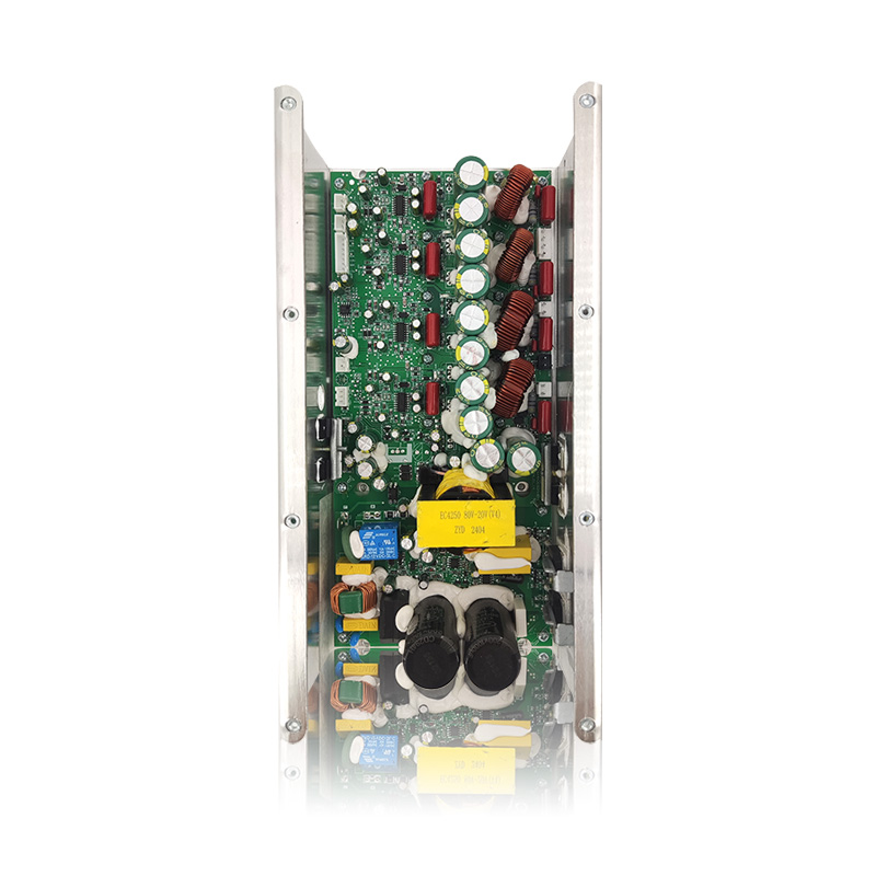
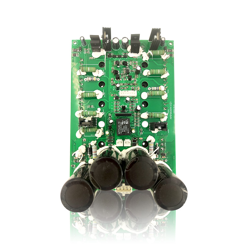
If the thermal budget of an AB design stops scaling, usually above a few hundred watts per channel inside a compact cabinet, the next step in professional audio is not back to Class A but forward to Class H, which switches the supply rail in step with the signal. A module such as the AMP400H keeps a linear-transformer supply and a U-shaped aluminium heatsink, retaining the analogue output stage while cutting dissipation at low and mid levels.
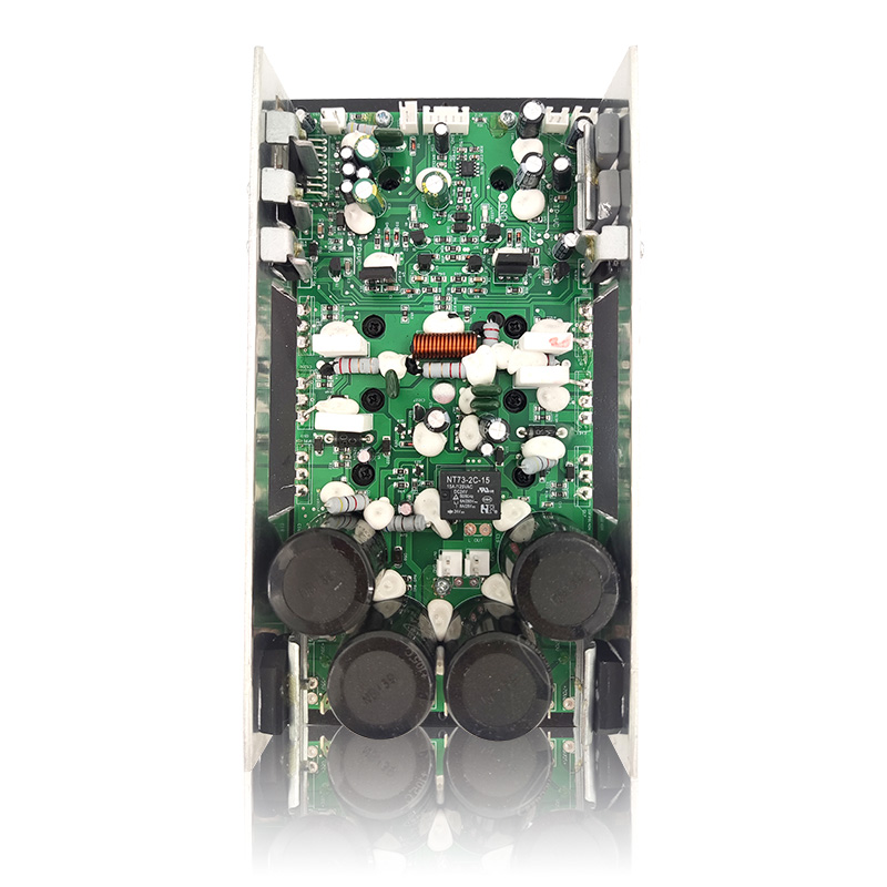 AMP400H+7294 Class H Power Amplifier ModuleA Class H module with 400 W mid/low and 100 W high-frequency outputs, a linear-transformer supply and U-shaped heatsink, plus multiple protection circuits.View Product →
For teams mapping the whole family before committing, our guide to amplifier classes A, AB, D and H for powered speaker module design walks through the same trade-offs for each topology. You can also browse the current Class AB loudspeaker amplifier modules to compare output levels and supply options.
Choosing Between Them for a New Product
Four questions usually settle the decision faster than any listening test:
- What is the duty cycle? A speaker that runs eight hours at high output cannot afford a stage that dissipates its full bias power the entire time.
- Where does the heat go? In a sealed plastic enclosure, an AB design already needs a thermal path to the plate; Class A would need a far larger one.
- At what level is distortion actually audible? Measure at the levels the product will really play at, not at 1 W into a dummy load.
- What does the finished unit weigh? Transformer and heatsink mass is a recurring freight and installation cost, not a one-off.
Answer those honestly and the bias point, along with the module platform, tends to choose itself.
Frequently Asked Questions
Q1. What is the main difference between a Class A and a Class AB amplifier?
Only the bias point. A Class A output stage conducts through the whole signal cycle; a Class AB stage conducts for roughly 200 degrees per device, which removes crossover distortion while using far less standing current.
Q2. Is Class A really better than Class AB for sound quality?
Not automatically. A well-biased Class AB module will usually measure and sound better than a poorly built Class A amplifier. Class A only has a clear edge at very low levels into high-sensitivity speakers.
Q3. Why do Class A amplifiers run so hot?
Because the bias current flows continuously, whether or not there is a signal. Idle dissipation is close to full-load dissipation, so the heatsink must be sized for the worst case at all times.
Q4. Which is more efficient, Class A or Class AB?
Class AB by a wide margin. Typical figures are 15-30% for Class A against 50-70% for Class AB at full power, and the gap at idle is even larger.
Q5. Can a Class AB power amplifier module drive a subwoofer?
Yes, especially in bridge-tied load configuration. Check the module's rated load impedance and confirm the supply and heatsink can sustain continuous low-frequency output rather than short bursts.
Q6. How do I size the power supply and heatsink for a Class AB module?
Start from the rated output power, divide by realistic efficiency to get input power, then subtract the audio output to find dissipation. Size the transformer for roughly 1.5 to 2 times the rated output and keep heatsink thermal resistance below the calculated limit.